
Menu:
Physical Modelling of Room Acoustics
In the last years different software applications intended to simulate, modeling or/and analyzing the acoustics of a room have emerged. These applications can be classified attending to two different aspects: the application target and market of the software tool and the numerical approximation method they use.
Application targets of this software tools are various: in building acoustics help to simulate the acoustic of an auditorium or concert hall before its building or to analyze how modifications to an existing room would improve or get worse the sound; in the public address systems, to assist in the placement of the loudspeakers or loudspeaker arrays and to optimize the performance of the acoustic pressure projected to the audience [4]; and finally they give support in the design of listening rooms and loudspeakers placement at home or in professional sound studios.
Attending to the approximation method, the most used approaches for developing todays commercial software applications are based into geometrical methods: Image Model Methods and Ray Tracing (and derived improvements as beam tracing, pyramid tracing, etc). However, these methods are not very precise on to simulate the behavior of the room at low frequencies, where the wavelength is comparable to the wall dimensions. Additionally, improvements, such as the inclusion of diffraction effects , have been added to some applications in order to overcome this drawback.
Although there exist precise numerical methods in frequency domain as finite-element method (FEM) and boundary-element method (BEM) , they are not the most interesting when the room impulse response is desired because the obtained solution is only valid for steady analysis, so translation to time domain for obtaining the impulse response is rather difficult. The Finite-Difference Time-Domain approximation method has been introduced into acoustics to solve field problems numerically in the last years . It is based on a finite-difference approximation of both the space and time derivatives and presents some clear advantages that will be commented later in the paper. However, the huge computer power needed to simulate large rooms has meant that today there have not appear commercial applications that uses FDTD for room acoustic modeling, being the major part based on ray-tracing.
In this reserach line, we are working in order to develop implementing a software application for room acoustic modeling. The stages include steps from the treatment of the architectural model, to the final result in the form of impulse response of the room. The method for the FDTD 3D mesh generation is addressed, also the parallelization of the algorithm and the different architectures that can be employed.
Example of simulation
Consider the building of the figure. It has 60×40×20 meters. Because is a huge building and in order to maintain reasonable computational resources, we want to simulate the acoustics only to 500 Hz. Therefore we have fs=4 kHz and deltax=0.147 and the number of cells will be 408×272×136 = 15,092,736 cells.
To carry on the simulation a Gaussian source has been placed in the middle of the building. The walls have been considered as perfect reflecting walls for simplicity. A simulation of one second has been run. Using a multiple core computer, the simulation has taken less than one minute.
Once finished the simulation, a 2D horizontal slice of the pressure matrix has been exported for visualization purposes. The second figura shows the resulting pressure map of this section of the building. Although in this example we choose a big building and a low frequency, for smaller enclosures, it is possible to reach higher maximum frequencies using reasonable computer resources.
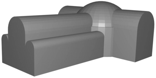
Building used in the example of simulation (size 60×40×20 meters)
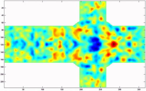
Resulting pressure map of a section of the building after a simulation of 1 second using a Gaussian pulse source in the middle of the building