
PROBLEM
The structure of a chair is represented in Figure 1. The pipe is made of steel and has a thickness of 2 mm.

Figure 1. Structure of the chair.
The radius of curvature in the structure is 100 mm for all pipes and another dimensions of the chair are represented in mm in Figure 1.
Table 1 indicates the mechanical properties for the steel S-275 JR and for the aluminium 6061 T6.
Table 1. Material properties.
| Steel S 275 JR | Aluminium 6061 T6 | ||
| Esteel | 210 GPa | Ealuminium | 73 GPa |
| Sy steel | 275 MPa | Sy aluminium | 275 MPa |
| νsteel | 0.3 | νaluminium | 0.33 |
Plastic deformation is the design criteria for this particular problem. A force of 800 N acts vertically on the intersection of the tubes, and a force of 400 N acts horizontally at the back.
GEOMETRY OF THE MODEL
First of all, define a name for the problem: "Chair".
Utility Menu > File > Change Title
And define the problem as "Structural":
Main Menu > Preferences > Structural
The element type is "PIPE 2 node 288":
Main Menu > Preprocessor > Element Type > Add/Edit/Delete
Now, define the mechanical properties for the Steel S-275 JR (Figure 2).
Main Menu > Preprocessor > Material Props > Material Models
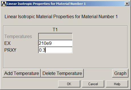
Figure 2. Mechanical properties for the Steel S-275 JR.
Next, input the geometric characteristics of the cross section. As a first approach, consider a diameter of 20 mm (Figure 3).
Main Menu > Preprocessor > Sections > Pipe > Add
Define "Pipe" as "Section name" and ID = 1.
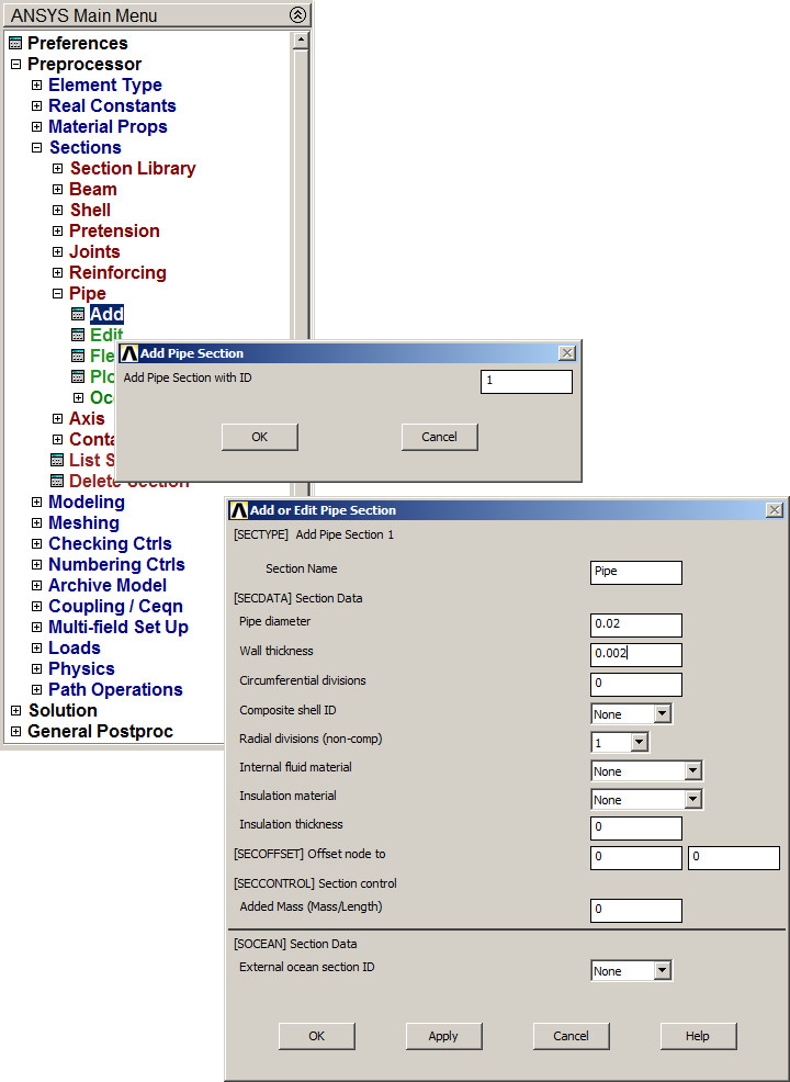
Figure 3. Input geometric characteristics for "Pipe".
Plot the geometry of the circular cross section (Figure 4).
Main Menu > Preprocessor > Sections > Pipe > Plot Section
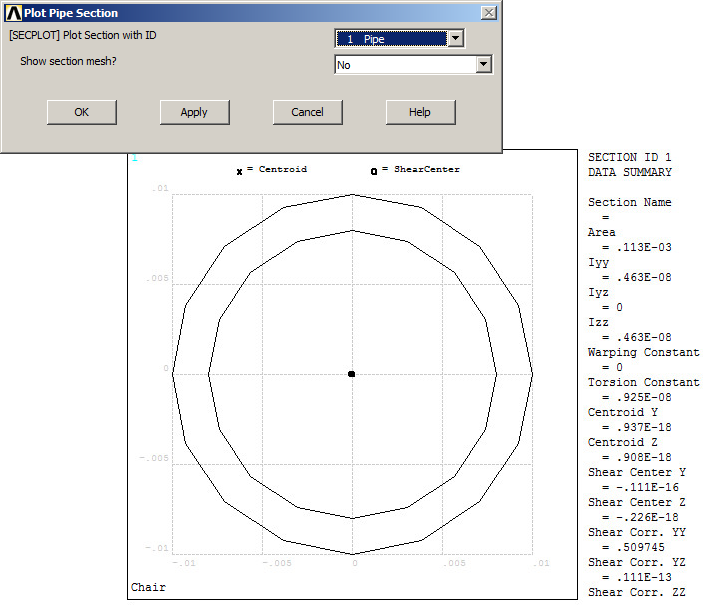
Figure 4. Geometry of the circular cross section.
For this particular problem, change the orientation for the axes:
Utility Menu > PlotCtrls > View Settings > Viewing Directions
And select "Z-axis up".
Now, create the keypoints according to the coordinates indicated in Table 2:
Main Menu > Preprocessor > Modeling > Create > Keypoints > In Active CS
Table 2. Keypoints coordinates.
| Keypoint | X (m) | Y (m) | Z (m) |
| 1 | 0 | 0 | 0 |
| 2 | 0 | 0.5 | 0 |
| 3 | 0.4 | 0.5 | 0 |
| 4 | 0.4 | 0 | 0 |
| 5 | 0 | 0 | 0.5 |
| 6 | 0 | 0.5 | 0.5 |
| 7 | 0.4 | 0.5 | 0.5 |
| 8 | 0.4 | 0 | 0.5 |
| 9 | 0.2 | 0.25 | 0.5 |
| 10 | 0 | 0 | 0.8 |
| 11 | 0 | 0.25 | 0.8 |
| 12 | 0 | 0.5 | 0.8 |
Figure 5 represents the created keypoints.
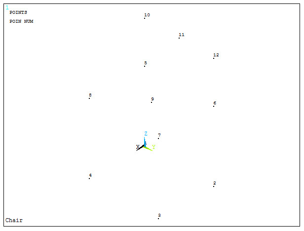
Figure 5. Keypoints for the chair.
Now, create the lines between the keypoints:
Main Menu > Preprocessor > Modeling > Create > Lines > Straight Line
Lines must be created in the order indicated in Table 3.
Table 3. Defining Lines.
| Line | First keypoint | Second keypoint |
| 1 | 1 | 2 |
| 2 | 2 | 3 |
| 3 | 3 | 7 |
| 4 | 7 | 9 |
| 5 | 9 | 5 |
| 6 | 5 | 10 |
| 7 | 10 | 11 |
| 8 | 11 | 12 |
| 9 | 12 | 6 |
| 10 | 6 | 9 |
| 11 | 9 | 8 |
| 12 | 8 | 4 |
| 13 | 4 | 1 |
Figure 6 represents the graphic screen with the lines for the structure.
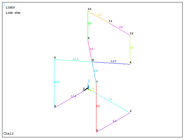
Figure 6. Graphic screen with the lines for the structure.
Define the radius of curvature with the option "Line Fillet" (Figure 7):
Main Menu > Preprocessor > Modeling > Create > Lines > Line Fillet
The radius is 0.1 m. Select the corresponding lines and define the radius.
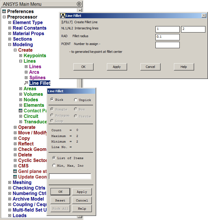
Figure 7. Defining "Fillet radius".
Figure 8 represents the geometric model of the chair.
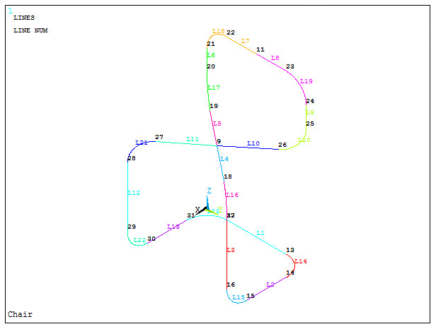
Figure 8. Geometric model of the chair.
Now, mesh the model:
Main Menu > Preprocessor > Meshing > Size Cntrls > ManualSize > Lines > All Lines
The element size is 0.005 m, as indicated in Figure 9.
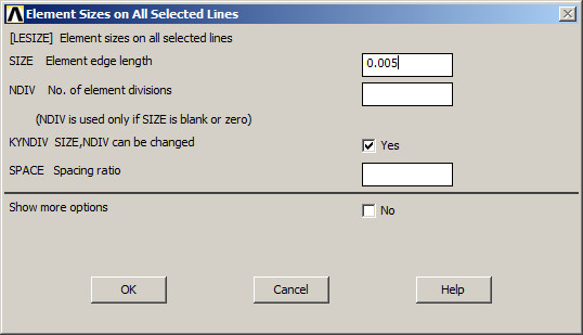
Figure 9. Defining the element size.
Finish the meshing process:
Main Menu > Preprocessor > Meshing > Mesh > Lines > Pick All
The model can be scaled (Figure 10):
Utility Menu > PlotCtrls > Style > Size and Shape
Activate "On" in "ESHAPE".
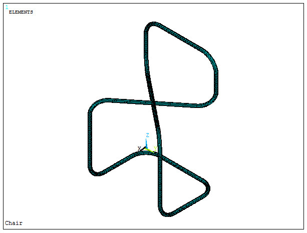
Figure 10. Scaled model.
LOADS AND BOUNDARY CONDITIONS
For the boundary conditions, restrict the displacements of the four keypoints located at the end of the members contacting the floor. These keypoints are 30, 31, 14 and 15, according to Figure 8.
Keypoint 31 is restricted in UX, UY and UZ directions (Figure 11).
Main Menu > Preprocessor > Loads > Define Loads > Apply > Structural > Displacement > On Keypoints
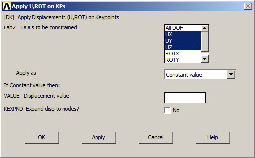
Figure 11. Restrictions at keypoint 31.
Now, restrict displacements in UX and UZ at keypoint 14 (Figure 12).
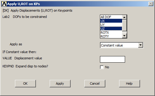
Figure 12. Restrictions at keypoint 14.
Finally, restrict displacement in UZ direction at keypoints 15 and 30 (Figure 13).
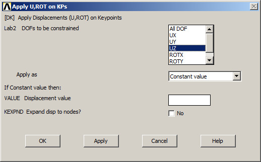
Figure 13. Restrictions at keypoints 15 and 30.
Now, apply the forces on keypoints 9 and 11:
Main Menu > Preprocessor > Loads > Define Loads > Apply > Structural > Force/Moment > On keypoints
And apply a force of -800 N at FZ direction on keypoint 9 (Figure 14).

Figure 14. Applying a force on keypoint 9.
In the same way, apply a force of -400 N in FX direction on keypoint 11 (Figure 15).
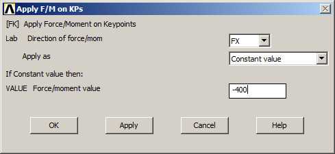
Figure 15. Applying a force on keypoint 11.
Figure 16 represents the model of the chair with the loads and boundary conditions.
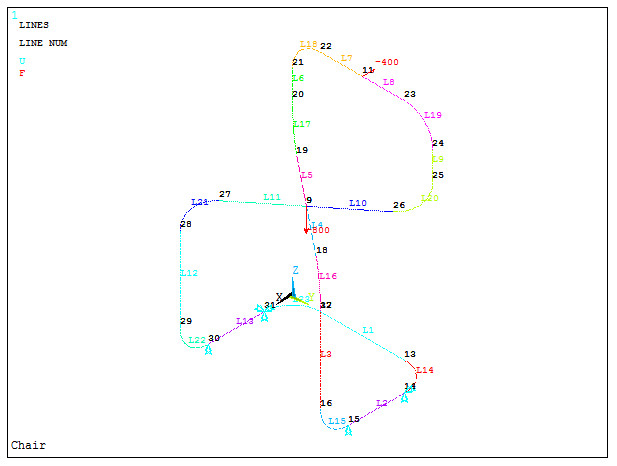
Figure 16. Model of the chair with the loads and boundary conditions.
SOLUTION
Solve the problem:
Main Menu > Solution > Solve > Current LS
Click "OK". "Solution is done!".
RESULTS
Now, evaluate the stress distribution in the model.
Main Menu > General Postproc > Plot Results > Contour Plot > Nodal Solu
Select "von Mises stress" (Figure 17).
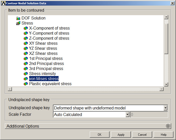
Figure 17. "von Mises stress".
Figure 18 represents the stress distribution in one part of the chair.

Figure 18. Stress distribution in one part of the chair.
When the maximum stress is higher than the allowable stress, change the section properties. Figure 19 indicates the definition of a new pipe with a diameter of 26 mm and a thickness of 2 mm. Edit the section:
Main Menu > Preprocessor > Sections > Pipe > Edit
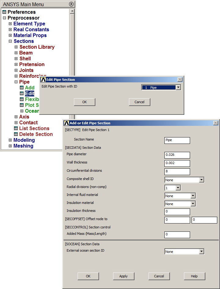
Figure 19. Changing the section properties.
Solve the problem. The new results are represented in Figure 20.
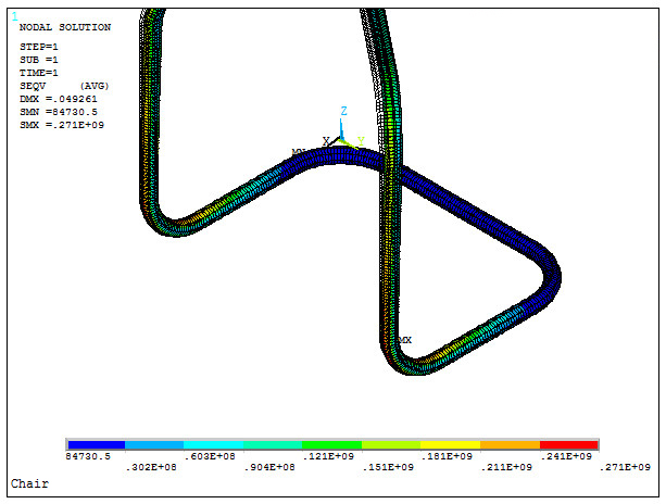
Figure 20. Results for the new section.
Finally, evaluate the problem for the aluminium 6061 T6. Figure 21 shows the definition of the new material.
Main Menu > Preprocessor > Material Props > Material Models
Define "Material Model Number 2".
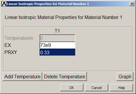
Figure 21. Material properties for the aluminium 6061 T6.
Assign the new material to the structure:
Main Menu > Preprocessor > Modeling > Move/Modify > Elements > Modify Attrib
Select "Pick All". After that, material number 2 is defined.
Solve again the problem. Figure 22 represents the new results for the stress distribution.
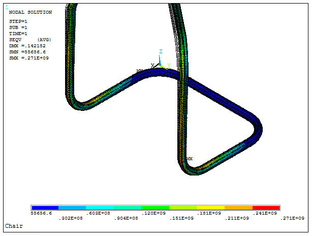
Figure 22. Stress distribution for structure with the aluminium 6061 T6.