
PROBLEM
Figure 1 represents a shaft support model. A force of 5000 N is acting on the swivels. Determine the deformed shape and the stress distribution in this mechanical component. Compare the results when modifying the geometry by means of a radius of curvature of 10 mm at the joint between the two main parts of the model.
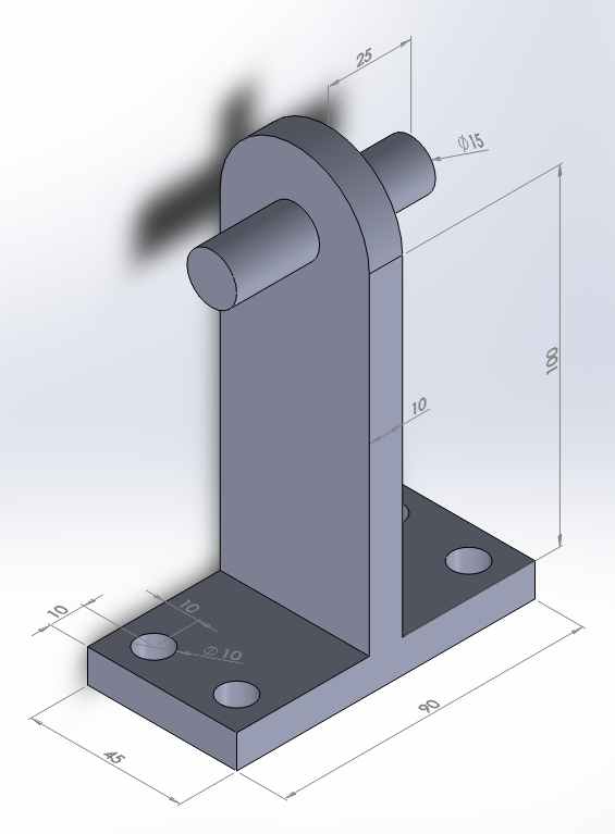
Figure 1. Shaft support model.
Table 1 indicates the mechanical properties of the stainless steel.
Table 1. Material properties.
| Stainless steel AISI 304 | |
| EStainless steel | 190 GPa |
| νStainless steel | 0.3 |
GEOMETRY OF THE MODEL
First of all, define the analysis type:
Main Menu > Preferences
Activate "Structural".
Now, change the jobname for this particular problem: "Shaft support".
Utility Menu > File > Change Jobname
The element type for this problem is "SOLID 10 node 187" (Figure 2).
Main Menu > Preprocessor > Element Type > Add/Edit/Delete
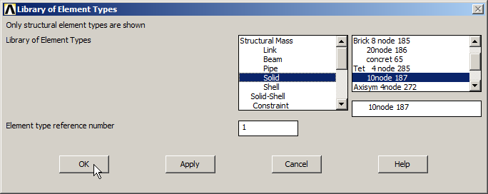
Figure 2. Element type: "SOLID 10 node 187".
Define the mechanical properties of the stainless steel: modulus of elasticity (EX) and Poisson's ratio (PRXY):
Main Menu > Preprocessor > Material Props > Material Models
The material is defined as "Structural – Linear – Elastic – Isotropic" (Figure 3).
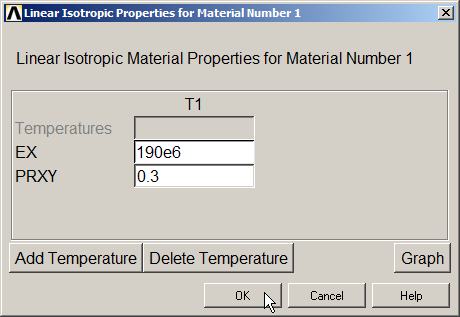
Figure 3. Material properties.
For the geometry of the model, set the Z-axis as the vertical one, as indicated in Figure 4:
Utility Menu > PlotCtrls > View Settings > Viewing Direction
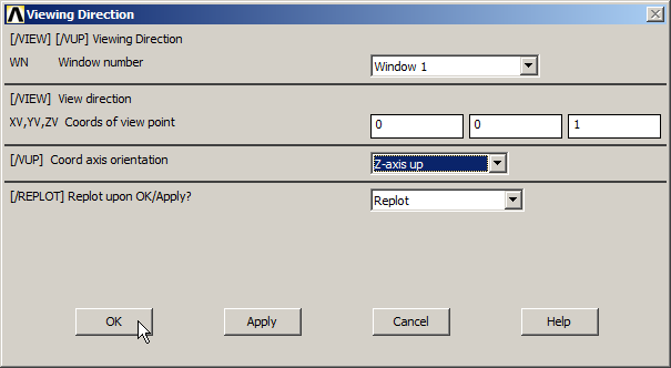
Figure 4. "Z-axis up" option.
And define a grid for the working plane. The geometric parameters for the grid are indicated in Figure 5.
Utility Menu > WorkPlane > WP Settings
The grid can be displayed on the screen with the option "Display Working Plane" from the "Utility Menu".
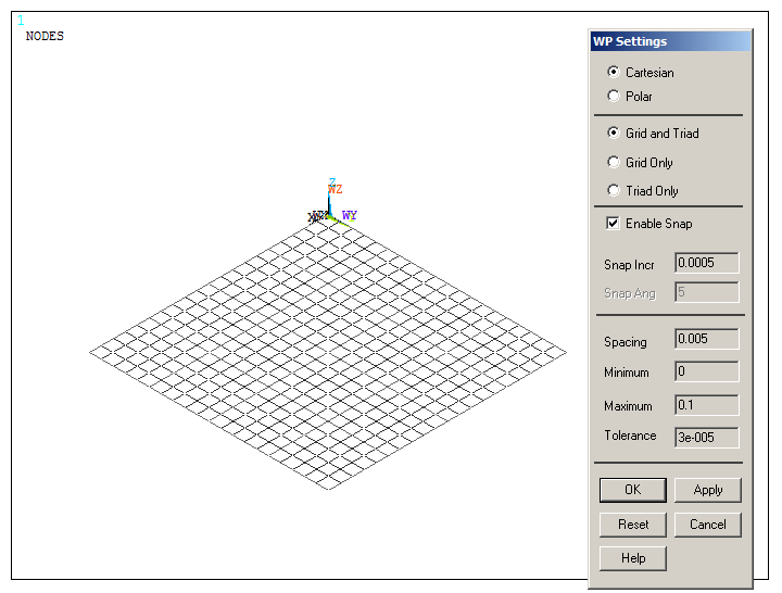
Figure 5. Grid parameters (WP Settings).
Now, create a rectangular prism.
Main Menu > Preprocessor > Modeling > Create > Volumes > Block > By 2 Corners & Z
The geometric characteristics for this volume are indicated in Figure 6.
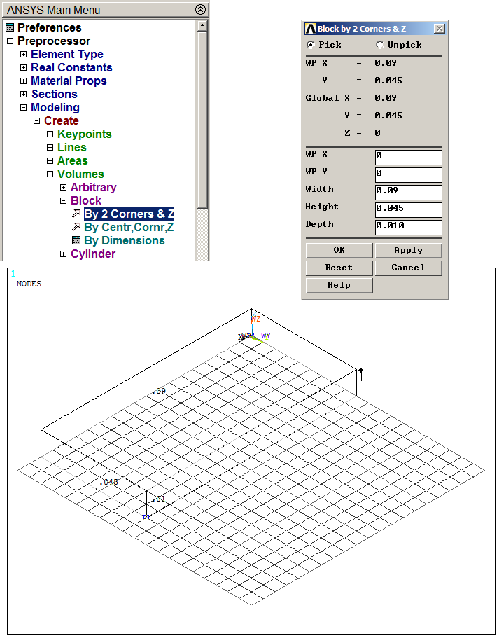
Figure 6. Creating a rectangular prism.
After that, create four solid cylinders for the circular holes. Figures 7, 8, 9 and 10 show this process and the geometric characteristics of the four cylinders.
Main Menu > Preprocessor > Modeling > Create > Volumes > Cylinder > Solid Cylinder
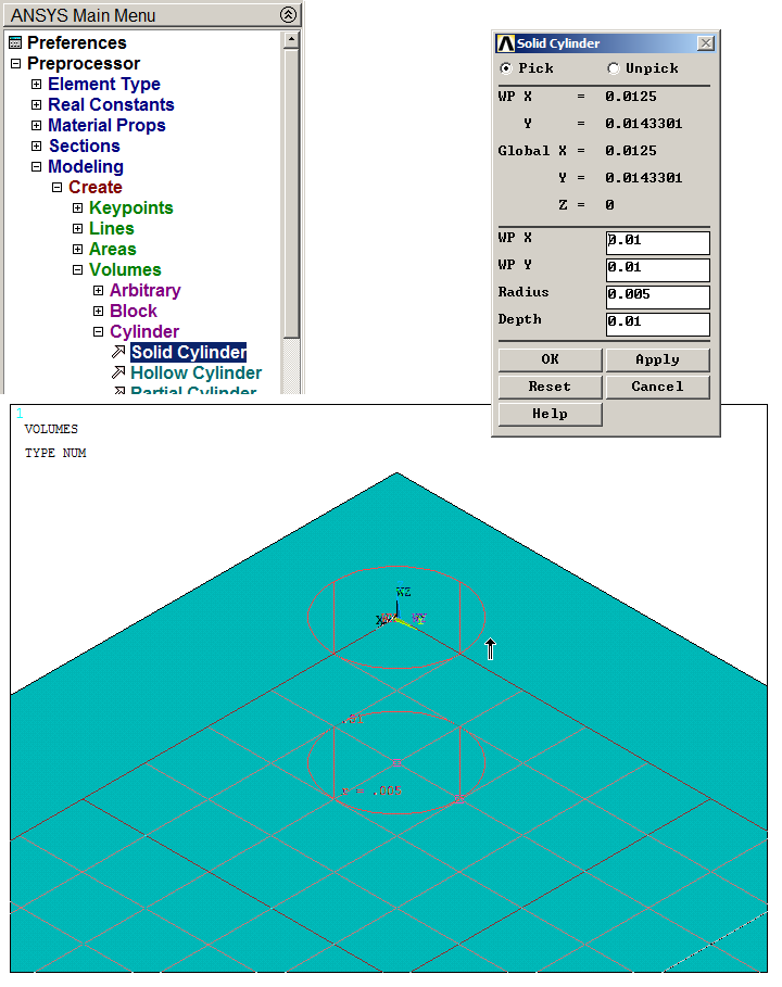
Figure 7. First solid cylinder.
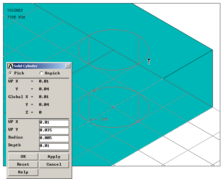
Figure 8. Second solid cylinder.
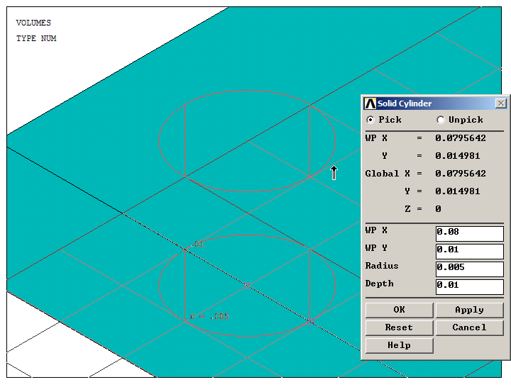
Figure 9. Third solid cylinder.
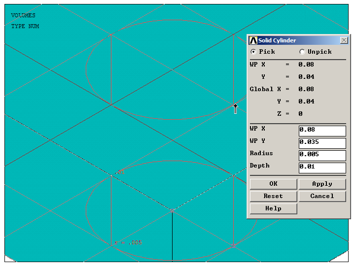
Figure 10. Fourth solid cylinder.
Figure 11 displays the rectangular block with the four solid cylinders. Now, subtract the cylinders to generate the circular holes:
Main Menu > Preprocessor > Modeling > Operate > Booleans > Subtract > Volumes
Click on the rectangular block, "OK", and then click on the four cylinders and "OK".
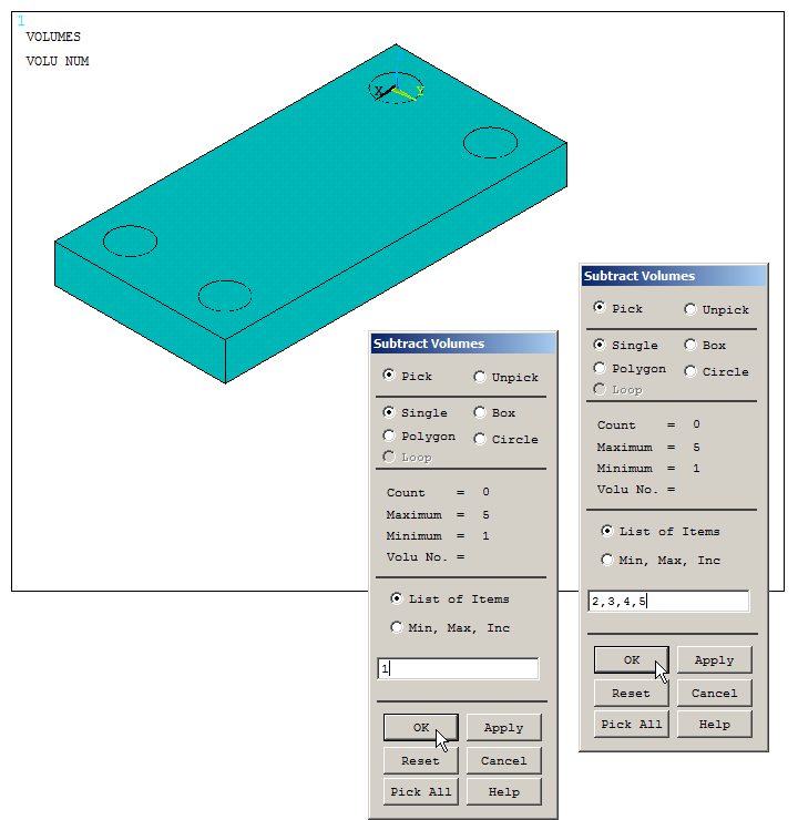
Figure 11. "Subtract Volumes" operation.
Now, number the keypoints from "Utility Menu – PlotCtrls – Numbering – Keypoints" and move the working plane at keypoint 5 (Figure 12).
Utility Menu > WorkPlane > Offset WP to Keypoints
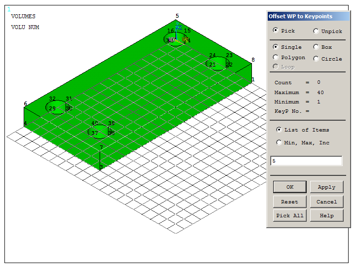
Figure 12. Moving the working plane at keypoint 5.
Create a second rectangular prism with the geometric characteristics indicated in Figure 13.
Main Menu > Preprocessor > Modeling > Create > Volumes > Block > By 2 Corners & Z
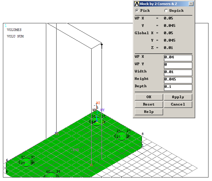
Figure 13. Creating the second rectangular prism.
Plot the lines of the model from "Utility Menu – Plot – Lines" and align the working plane with the vertical axis. For this operation three keypoints are required (Figure 14):
Utility Menu > WorkPlane > Align WP with KP
Select keypoints 45, 48 and 42 and "OK".
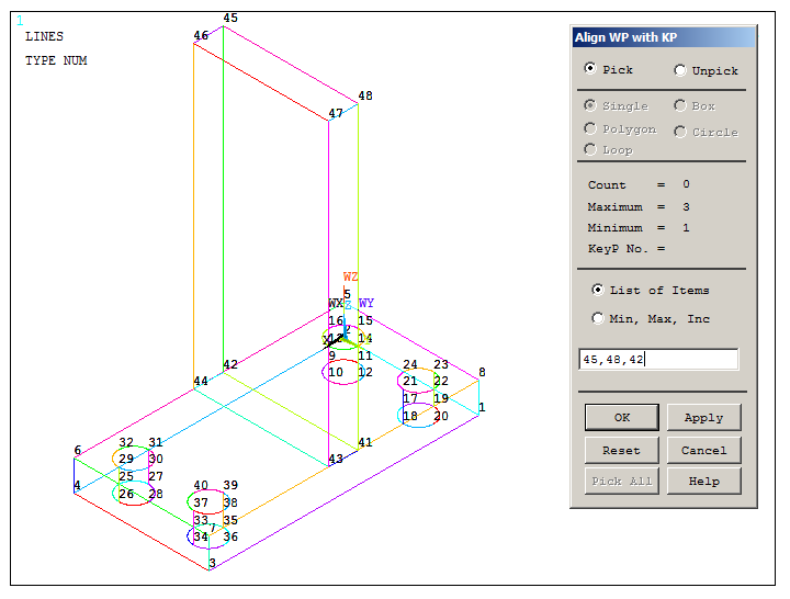
Figure 14. "Align WP with keypoints" operation.
Create a solid cylinder at the top of the shaft support as indicated in Figure 15.
Main Menu > Preprocessor > Modeling > Create > Volumes > Solid Cylinder
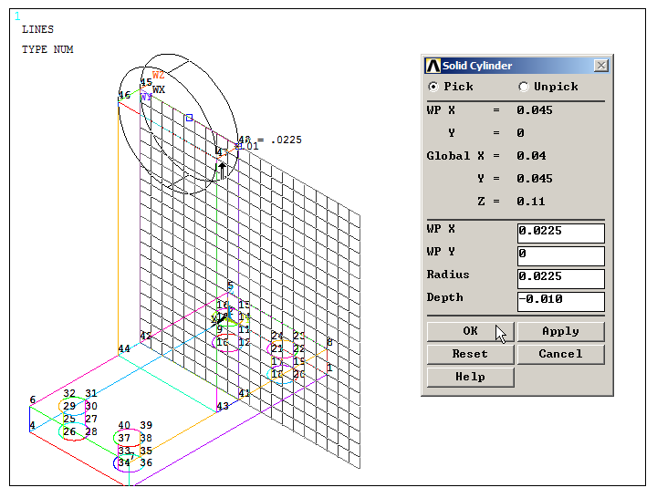
Figure 15. Solid cylinder at the top of the shaft support.
Next, create the two swivels. Figure 16 represents the creation of one of these two cylindrical components.
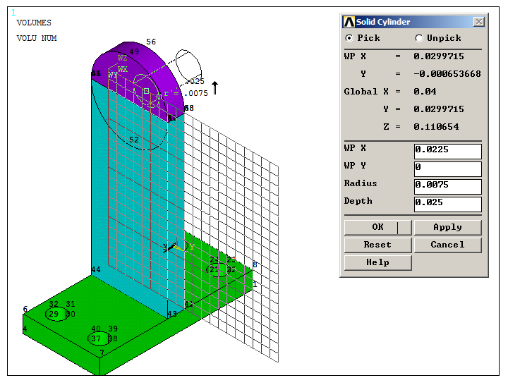
Figure 16. Geometric characteristics of the first swivel.
Since there are some coincident keypoints in the model, activate the option "Merge Items", as indicated in Figure 17.
Main Menu > Preprocessor > Numbering Ctrls > Merge Items
Select "Keypoints" in "Type of item to be merge".
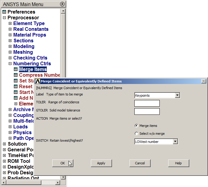
Figure 17. "Merge Items" option.
To create the cylindrical component at the other side of the model, move the working plane at keypoint 46, as indicated in Figure 18.
Utility Menu > WorkPlane > Offset WP to Keypoints
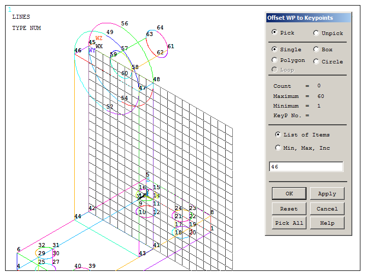
Figure 18. Moving the working plane at keypoint 46.
Figure 19 displays the creation of the other swivel.
Main Menu > Preprocessor > Modeling > Create > Volumes > Solid Cylinder
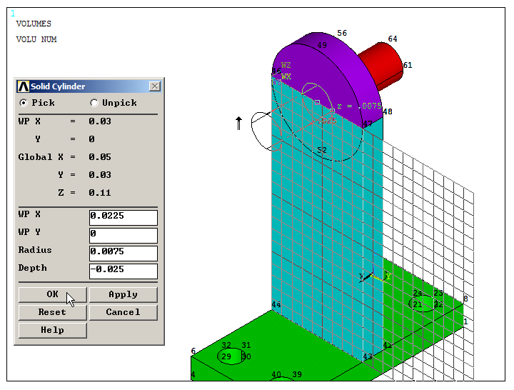
Figure 19. Geometric characteristics of the second swivel.
Plot the volumes from "Utility Menu – Plot – Volumes" and add the volumes, as indicated in Figure 20.
Main Menu > Preprocessor > Modeling > Operate > Booleans > Add > Volumes
Click "Pick All".
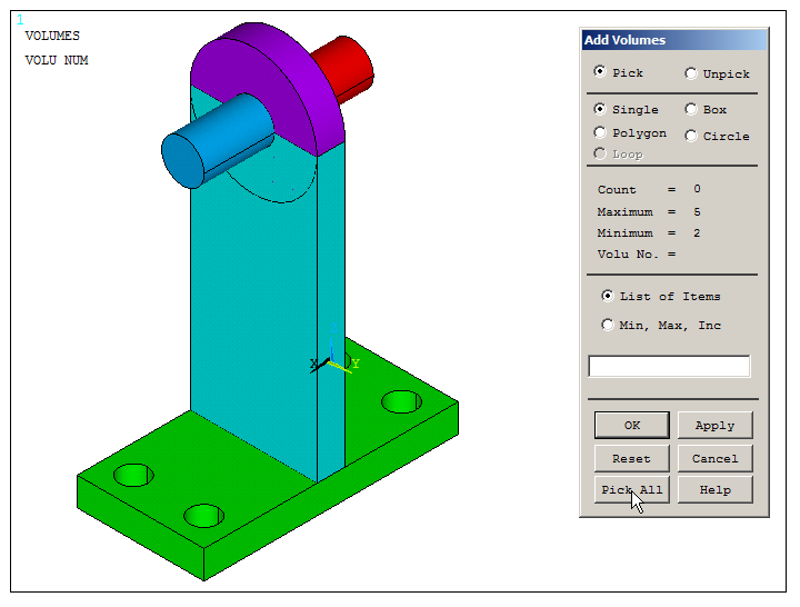
Figure 20. "Add Volumes" operation.
Now, change the orientation of the working plane:
Utility Menu > WorkPlane > Offset WP by Increments
Rotate the working plane 90º as indicated in Figure 21.
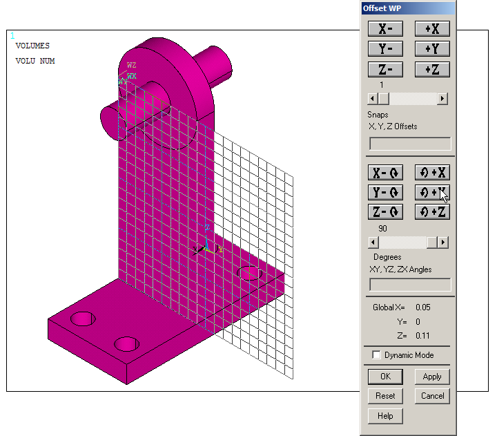
Figure 21. Rotate the working plane 90º.
And move the working plane 22.5 mm in Z direction (Figure 22), so that it is now located at the center of the model.
Utility Menu > WorkPlane > Offset WP by Increments
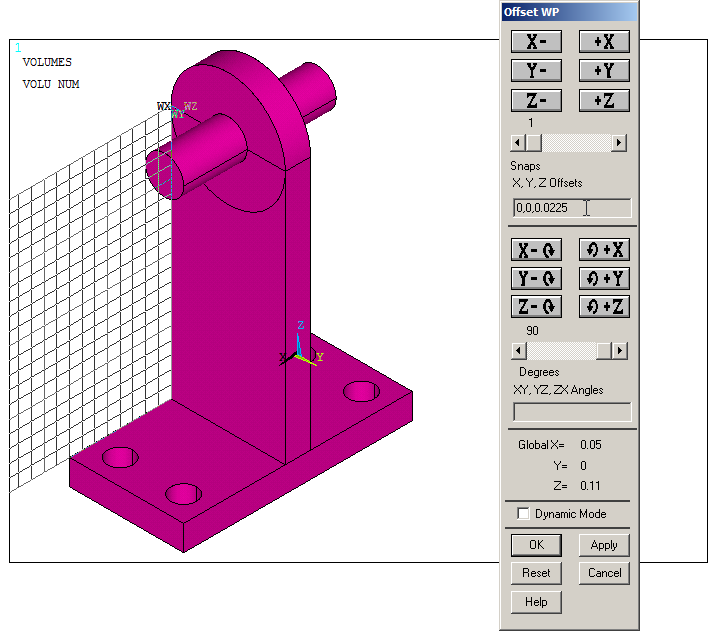
Figure 22. Moving the working plane 22.5 mm in Z direction.
The cylindrical components (swivels) must be divided in a number of areas to apply the force on the upper part. They are divided by the working plane (Figure 23).
Main Menu > Preprocessor > Modeling > Operate > Booleans > Divide > Area by WrkPlane
Click "Pick All" to divide the areas.
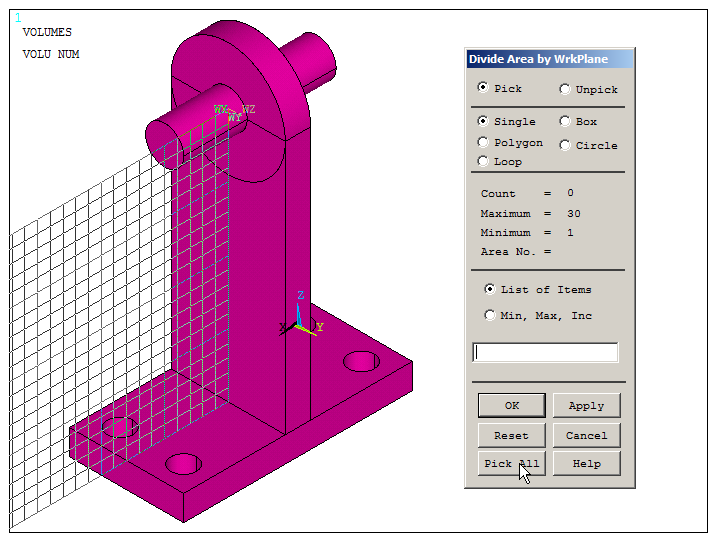
Figure 23. "Divide Area by WrkPlane".
The next step is to mesh the model. Define the element size as indicated in Figure 24. For this particular problem the element size is of 2.5 mm.
Main Menu > Preprocessor > Meshing > Size Cntrls > ManualSize > Global > Size
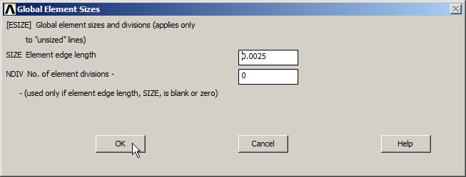
Figure 24. Element size for the mesh.
Finish the meshing process (Figure 25).
Main Menu > Preprocessor > Meshing > Mesh > Volumes > Free
And click "Pick All".
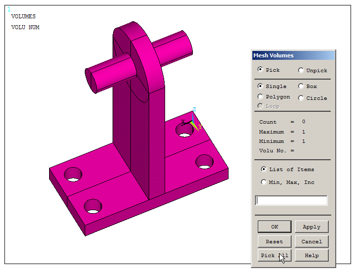
Figure 25. "Mesh Volumes" operation.
LOADS AND BOUNDARY CONDITIONS
The shaft support is fixed at the four cylindrical holes. So, restrict all degrees of freedom (All DOF) on the areas of these holes, as indicated in Figure 26.
Main Menu > Preprocessor > Loads > Define Loads > Apply > Structural > Displacement > On Areas
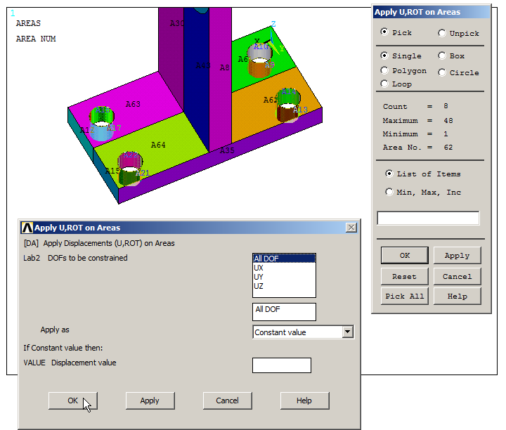
Figure 26. Restrict "All DOF" at the four holes.
The force is acting on the upper areas of the swivels. Select these areas from "Utility Menu – Select – Entities". These areas are A53, A60, A55 and A58, as displayed in Figure 27.
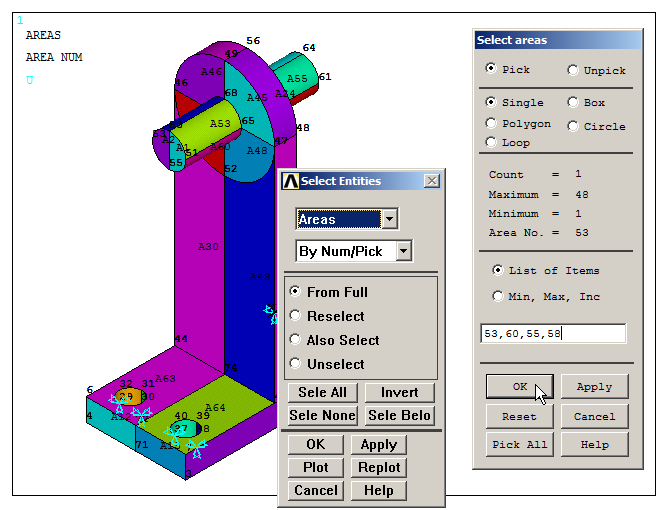
Figure 27. Select areas A53, A60, A55 and A58.
Plot the areas from "Utility Menu – Plot – Areas".
Then select the nodes attached to these areas as indicated in Figure 28.
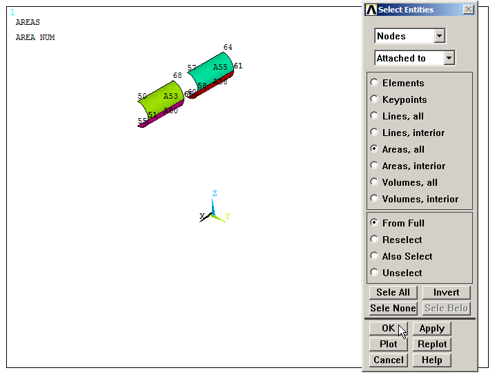
Figure 28. Select the nodes attached to the areas.
Figure 29 displays the selected nodes. Apply the force on the nodes:
Main Menu > Preprocessor > Loads > Define Loads > Apply > Force/Moment > On Nodes
Use "Box" option to select the nodes. There are 946 nodes.
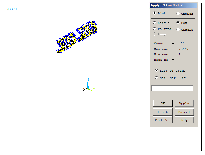
Figure 29. "Apply Force/Moment on Nodes".
The force of 5000 N must be distributed on the 946 nodes, as indicated in Figure 30.

Figure 30. Apply the distributed force in UY direction.
After the application of the force, select all the geometric entities:
Utility Menu > Select > Everything
Display the model from "Utility Menu – Plot – Replot".
SOLUTION
Solve the problem.
Main Menu > Solution > Solve > Current LS
"Solution is done!".
RESULTS
Figure 31 displays the deformed shape of this shaft support model.
Main Menu > General Postproc > Plot Results > Deformed Shape
Select the option "Def+undeformed".
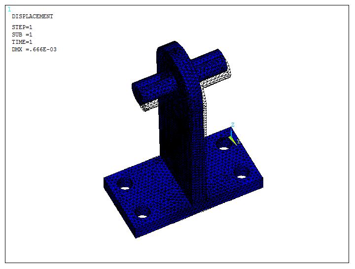
Figure 31. Deformed shape of the model.
Figure 32 represents the stress distribution.
Main Menu > General Postproc > Plot Results > Contour Plot > Nodal Solu
Select "Stress – von Mises stress".
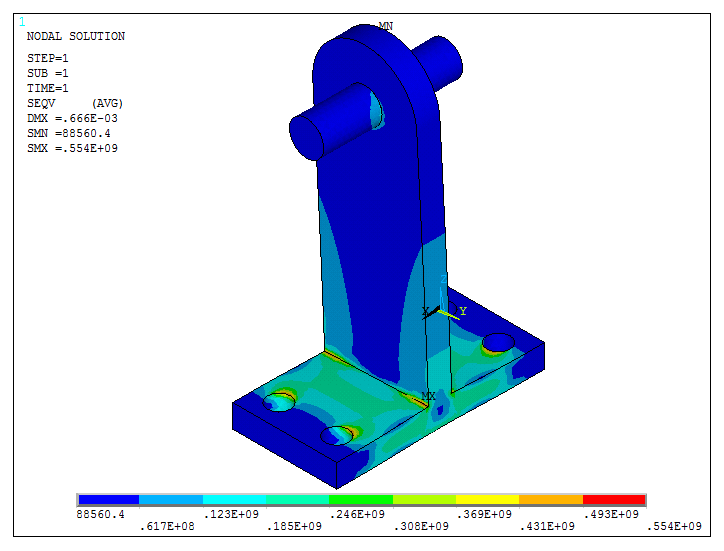
Figure 32. Stress distribution in the model.
After the evaluation of the results, modify the geometry including a fillet radius between the two rectangular prisms.
First of all, clear the mesh as indicated in Figure 33.
Main Menu > Preprocessor > Meshing > Clear > Volumes
After this operation, the forces attached to the nodes of the mesh are removed automatically, so they have to be redefined. The boundary conditions for the areas are not affected by this operation.
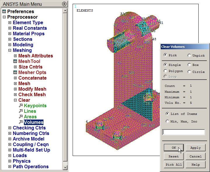
Figure 33. Clear mesh.
Plot the areas from "Utility Menu – Plot – Areas" and create the radius of curvature.
Main Menu > Preprocessor > Modeling > Create > Areas > Area Fillet
Figure 34 indicates the process to create these areas for the curvature. The radius is 0.01 m.

Figure 34. "Area Fillet" option.
Number the areas from "Utility Menu – PlotCtrls – Numbering – Areas" and create the new four lateral areas as indicated in Figure 35.
Main Menu > Preprocessor > Modeling > Create > Areas > Arbitrary > By Lines
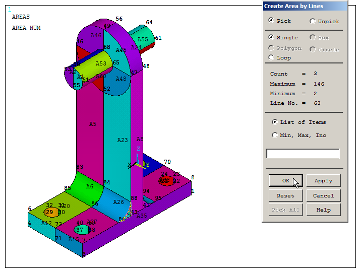
Figure 35. Create the new four lateral areas.
After that, create the new volumes, as indicated in Figure 36.
Main Menu > Preprocessor > Modeling > Create > Volumes > Arbitrary > By Areas
Select the areas that define each volume and "OK".
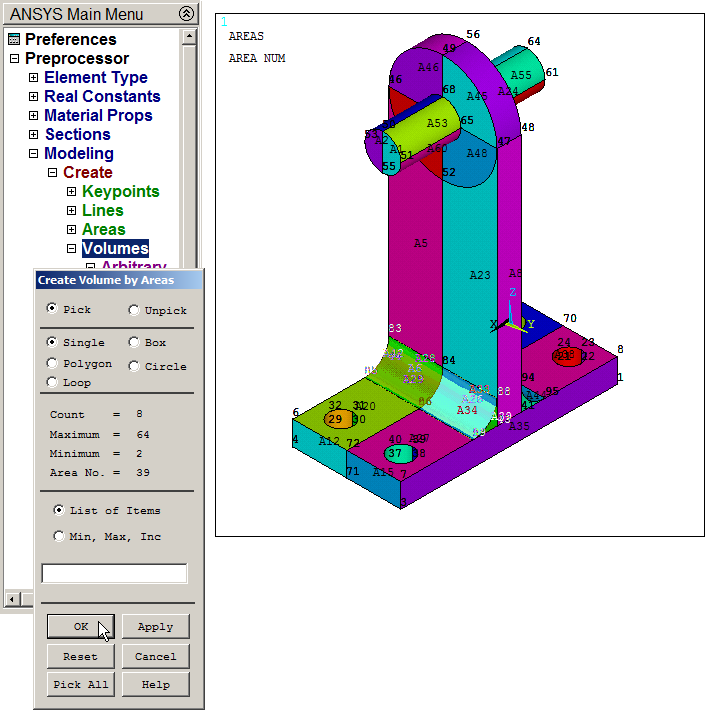
Figure 36. "Create Volumes by Areas" operation.
Finally, add the volumes (Figure 37).
Main Menu > Preprocessor > Modeling > Operate > Booleans > Add > Volumes
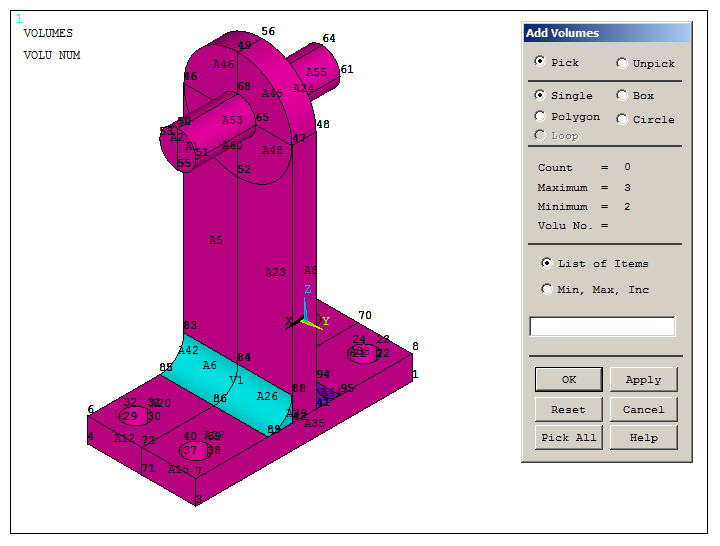
Figure 37. "Add Volumes" operation.
Mesh the new model of the shaft support and apply again the force (as explained before). Figure 38 displays the new meshed model.
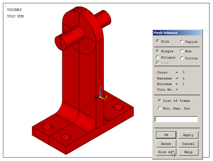
Figure 38. "Mesh Volumes" for the new model.
Figures 39 and 40 show the results of the deformation and the stress distribution, respectively. Evaluate how the variation in the geometry has influenced the results.
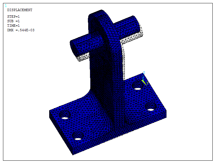
Figure 39. Deformed shape for the new model.
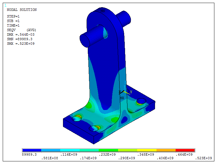
Figure 40. Stress distribution for the new model.