
PROBLEM
Figure 1 shows a rectangular box section with dimensions 80x40x4 mm. Define this particular section with ANSYS.
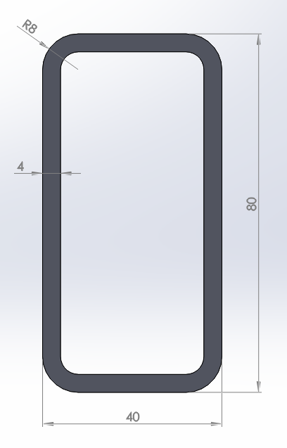
Figure 1. Rectangular box section.
GEOMETRY OF THE MODEL
First, define a name:
Utility Menu > File > Change Title
The name is "80x40x4" (Figure 2).
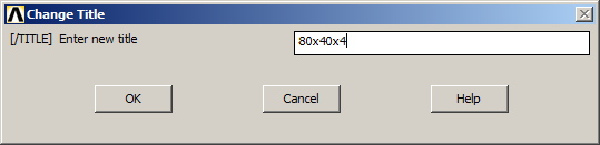
Figure 2. Change Title.
Input the eight keypoints that are indicated in Table 1.
Table 1. Keypoints coordinates.
| KEYPOINTS | X (m) | Y (m) |
| 1 | 0 | 0 |
| 2 | 0.04 | 0 |
| 3 | 0 | 0.08 |
| 4 | 0.04 | 0.08 |
| 5 | 0.004 | 0.004 |
| 6 | 0.036 | 0.004 |
| 7 | 0.036 | 0.076 |
| 8 | 0.004 | 0.076 |
Create the keypoints as indicated in Figure 3:
Main Menu > Preprocessor > Modeling > Create > Keypoints > In Active CS
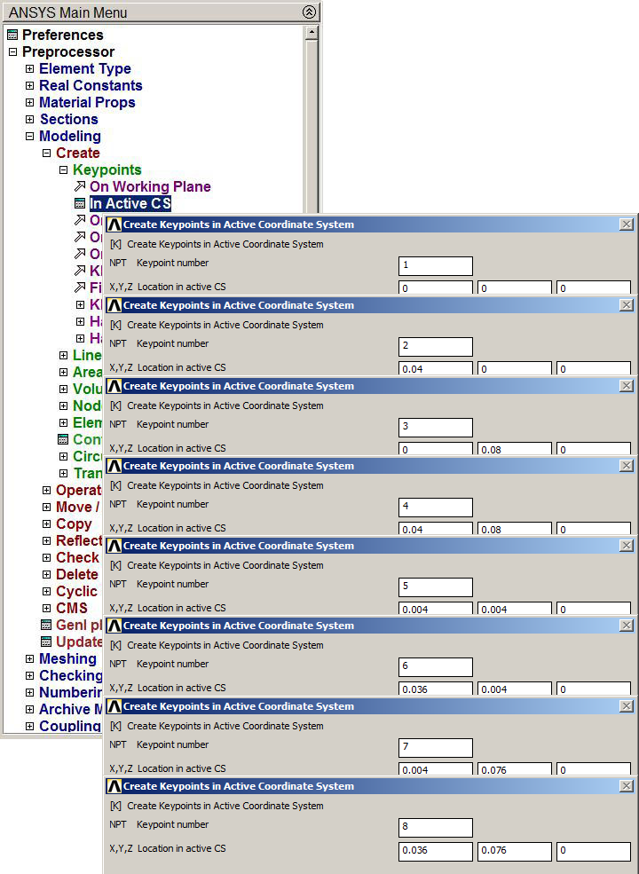
Figure 3. Create Keypoints.
Figure 4 represents the keypoints for the section.
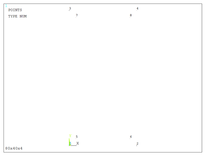
Figure 4. Graphic screen with the keypoints.
Now, define the lines as indicated in Figure 5:
Main Menu > Preprocessor > Modeling > Create > Lines > Straight Line
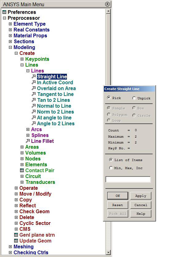
Figure 5. Defining lines.
Figure 6 represents the lines for the section.
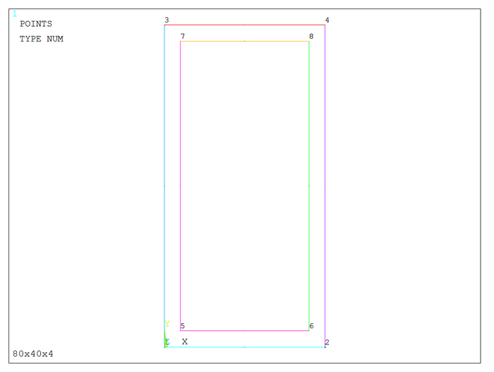
Figure 6. Graphic screen with the lines.
To define the radius of curvature on the corners of the rectangle, use the option "Line Fillet" (Figure 7):
Main Menu > Preprocessor > Modeling > Create > Lines > Line Fillet
For each corner of the rectangle, the outside radius is 0.008 m and the inside radius is 0.004 m.
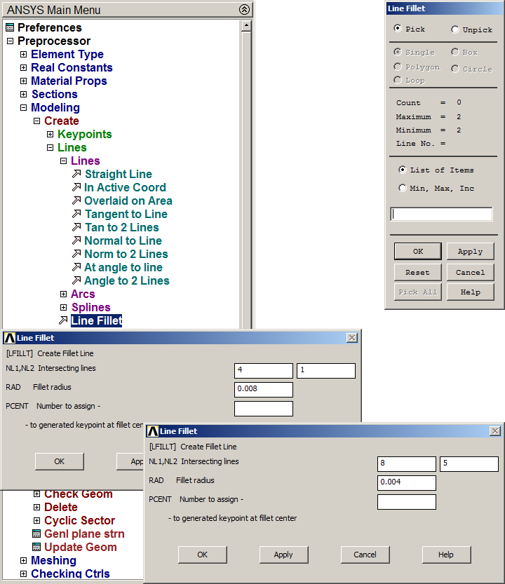
Figure 7. "Line Fillet" option.
Figure 8 represents the graphic screen with the lines that define the rectangular box section.
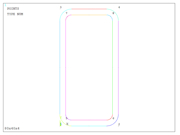
Figure 8. Geometry of the rectangular box section.
Now, create the area as indicated in Figure 9:
Main Menu > Preprocessor > Modeling > Create > Areas > Arbitrary > By Lines
Select the lines and click "OK".
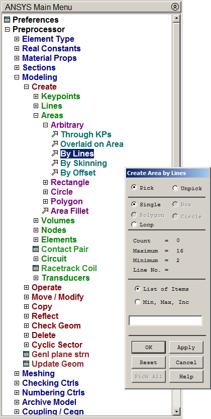
Figure 9. Creating the area.
The area for this particular section is represented in Figure 10.
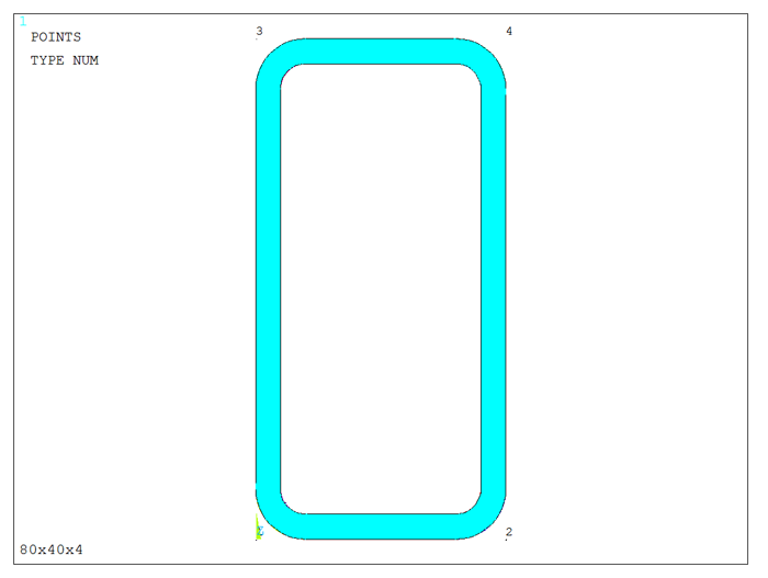
Figure 10. Area of the rectangular box section.
The created area must be meshed. First, define the element type, that is "PLANE 182", and then the element size is 0.002 m (Figure 11):
Main Menu > Preprocessor > Meshing > Size Cntrls > ManualSize > Areas > All Areas
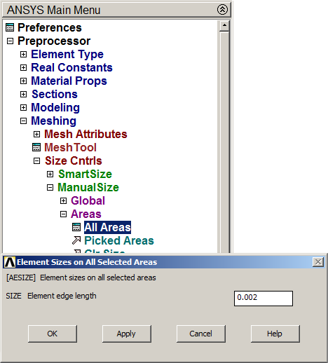
Figure 11. Meshing the area of the section.
Finish the meshing process:
Main Menu > Preprocessor > Meshing > Mesh > Areas > Free
Figure 12 represents the meshed area.
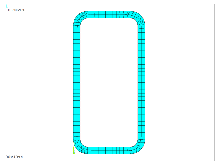
Figure 12. Meshed area.
Finally, save the model of the rectangular box section (Figure 13):
Main Menu > Preprocessor > Sections > Beam > Custom Sections > Write From Areas
Define a name for the section: "80x40x4".
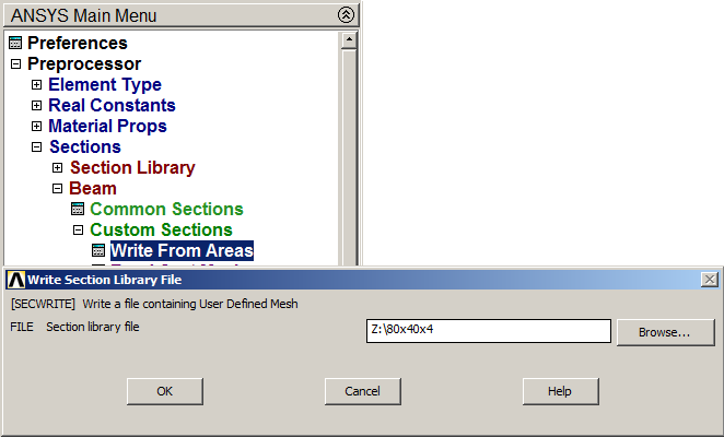
Figure 13. Saving the section with "Write From Areas" option.
PROBLEM
Figure 14 shows an L-shaped section with dimensions 40x40x2 mm. Define this particular section with ANSYS.
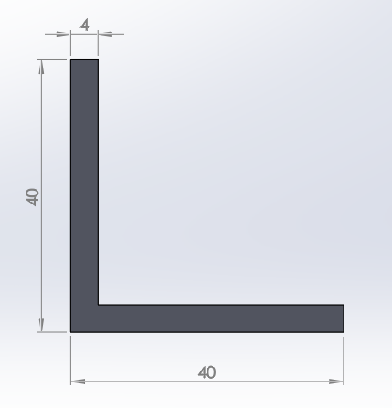
Figure 14. L-shaped section.
GEOMETRY OF THE MODEL
Define a name for the section:
Utility Menu > File > Change Title
The name is "L 40x4".
First of all, create a grid for the working plane, as indicated in Figure 15:
Utility Menu > Workplane > Display Working Plane
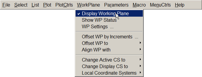
Figure 15. Display Working Plane.
Next, activate the option "Working Plane Settings" (Figure 16):
Utility Menu > WorkPlane > WP Settings
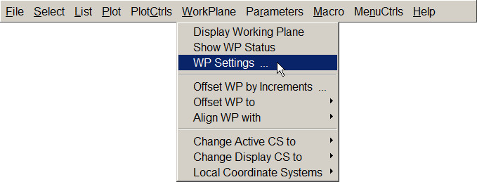
Figure 16. Working Plane Settings.
And create the grid with the parameters that are indicated in Figure 17.
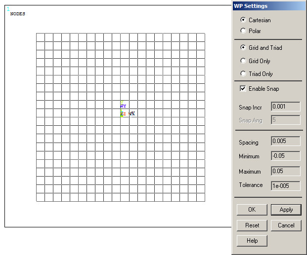
Figure 17. Parameters for the grid.
Now, define the first rectangle (Figure 18):
Main Menu > Preprocessor > Modeling > Create > Areas > Rectangle > By 2 Corners
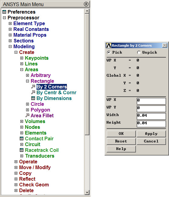
Figure 18. Creating the first rectangle.
Figure 19 represents the created area.
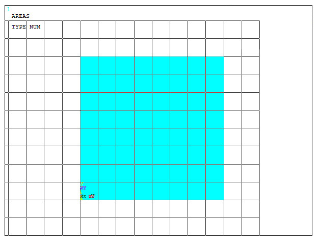
Figure 19. Rectangular area.
Then, create the second area, as indicated in Figure 20.
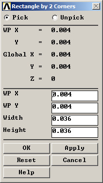
Figure 20. Parameters for the second area.
Define the L-shaped section by subtracting the second area as indicated in Figure 21.
Main Menu > Preprocessor > Modeling > Operate > Booleans > Subtract > Areas
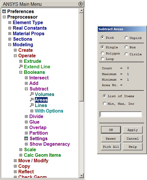
Figure 21. "Subtract Areas" option.
Figure 22 represents the model for the L-shaped section.
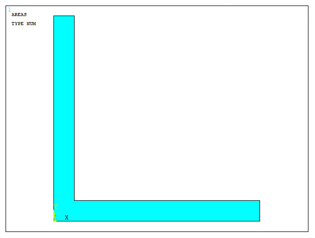
Figure 22. L-shaped section.
The created area must be meshed. First, define the element type:
Main Menu > Preprocessor > Element Type > Add/Edit/Delete
Select the element "Solid Plane 182".
Now, mesh the area (Figure 23):
Main Menu > Preprocessor > Meshing > Size Cntrls > ManualSize > Areas > Picked Areas
The element size is 2 mm.
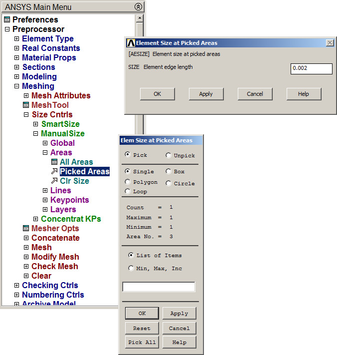
Figure 23. Meshing the area of the section.
Finish the meshing process:
Main Menu > Preprocessor > Meshing > Mesh > Areas > Free
Select the area and "OK".
This L-shaped section must be oriented at 45º. First, change the units:
Utility Menu > Parameters > Angular Units
Select "Degrees DEG" (Figure 24).
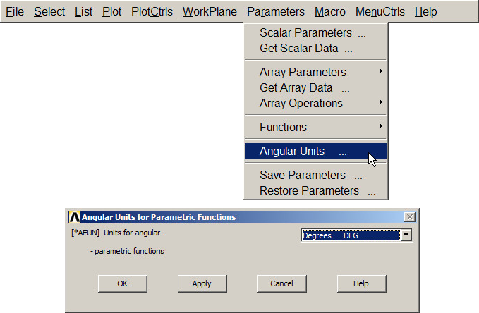
Figure 24. Select angular units.
Now select the cylindrical coordinate system (Figure 25):
Utility Menu > WorkPlane > Change Active CS to > Global Cylindrical
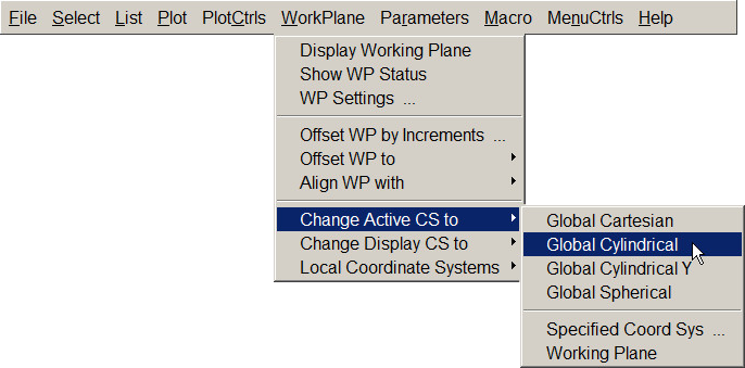
Figure 25. Global Cylindrical Coordinate System.
Next, rotate the section.
Main Menu > Preprocessor > Modeling > Move/Modify > Areas
Input the angle of 45º in "Y-offset in active CS" option (Figure 26).
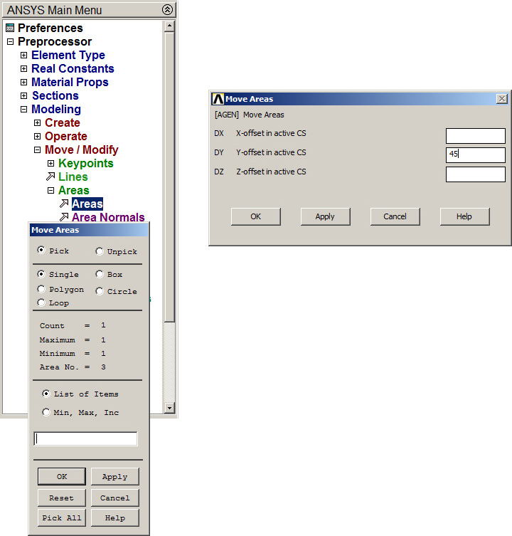
Figure 26. Rotate the section 45º.
Figure 27 displays the section with the new orientation.
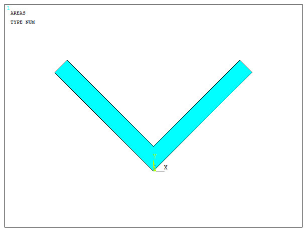
Figure 27. L-shaped section oriented at 45º.
Finally, save the L-shaped section (Figure 28):
Main Menu > Preprocessor > Sections > Beam > Custom Sections > Write From Areas
Define a name for the section: "L 40x4".
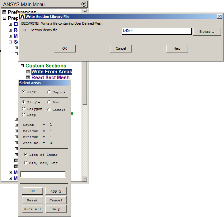
Figure 28. Saving the section "L 40x4".
Figure 29 shows the meshed section.
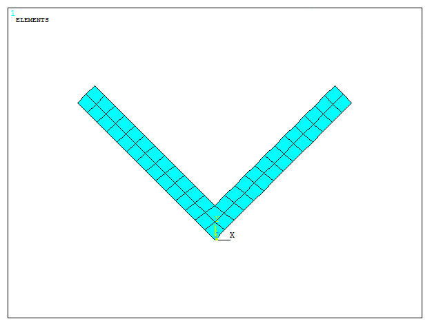
Figure 29. Meshed section.
Finally, obtain the geometric characteristics of the L-shaped section. First, read the section as indicated in Figure 30:
Main Menu > Preprocessor > Sections > Beam > Custom Sections > Read Sect Mesh
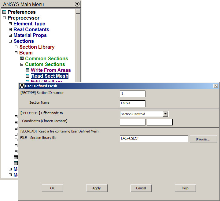
Figure 30. Read section "L 40x4".
Next, plot the section (Figure 31):
Main Menu > Preprocessor > Sections > Beam > Plot Section
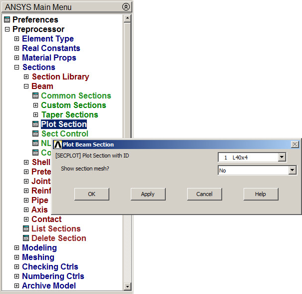
Figure 31. Plot section "L 40x4".
Figure 32 shows the section with its geometric characteristics.
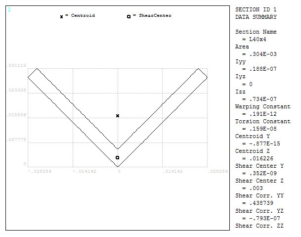
Figure 32. L-shaped section with its geometric characteristics.